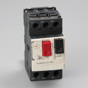
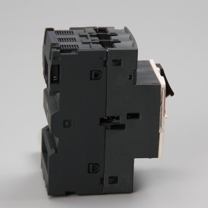
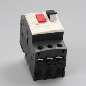
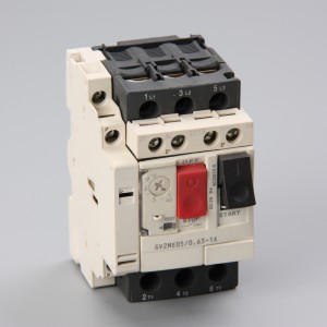
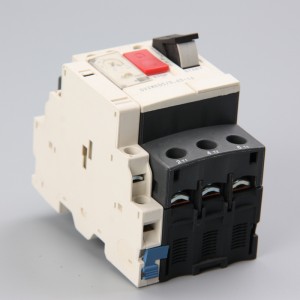
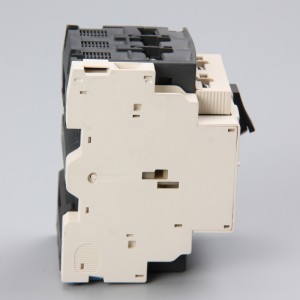
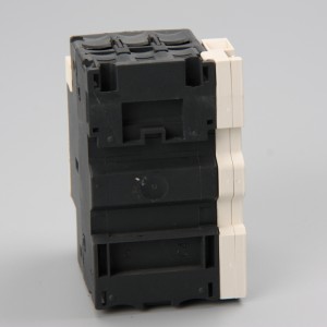
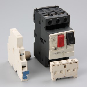
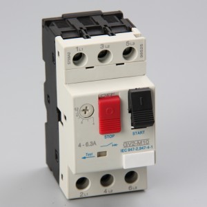
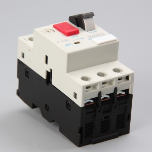
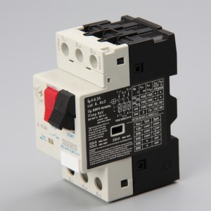
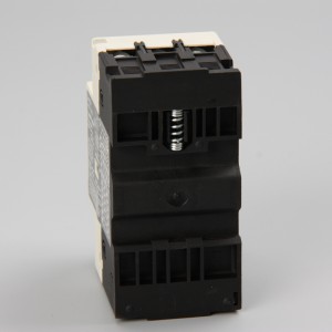
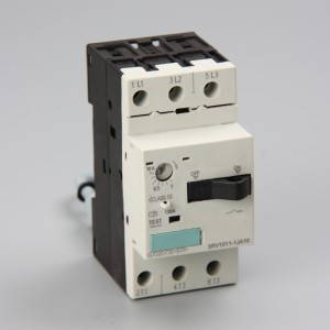
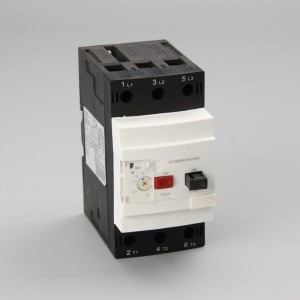
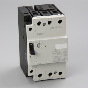
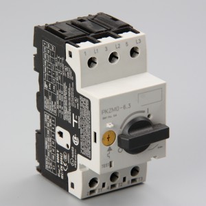
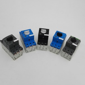
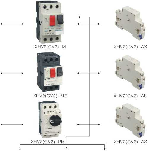
XHV2 (GV2)Motor protection circuit breaker
The model No.and meaning
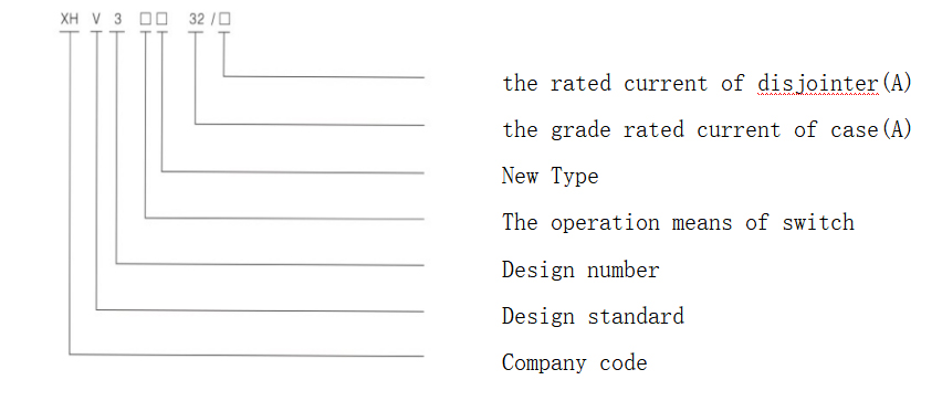
| Product model | Rated current InA | The adjusting range commuting current for coponents A. | The disjointing current commuting value in instant field InA | Order No. |
| GV2-M(ME) | 0.16 | 0.1-0.16 | 1.5 | XHV2-32(GV2)-M01C |
| 0.25 | 0.16-0.25 | 2.4 | XHV2-32(GV2)-M02C | |
| 0.4 | 0.25-0.4 | 5 | XHV2-32(GV2)-M03C | |
| 0.63 | 0.4-0.63 | 8 | XHV2-32(GV2)-M04C | |
| 1 | 0.63-1 | 13 | XHV2-32(GV2)-M05C | |
| 1.6 | 1-1.6 | 22.5 | XHV2-32(GV2)-M06C | |
| 2.5 | 1.6-2.5 | 33,5 | XHV2-32(GV2)-M07C | |
| 4 | 2.5-4 | 51 | XHV2-32(GV2)-M08C | |
| 6.3 | 4-6.3 | 78 | XHV2-32(GV2)-M10C | |
| 10 | 6-10 | 138 | XHV2-32(GV2)-M14C | |
| 14 | 9-14 | 170 | XHV2-32(GV2)-M16C | |
| 18 | 13-18 | 223 | XHV2-32(GV2)-M20C | |
| 23 | 17-23 | 327 | XHV2-32(GV2)-M21C | |
| 25 | 20-25 | 327 | XHV2-32(GV2)-M22C | |
| 32 | 24-32 | 416 | XHV2-32(GV2)-M32C |
| XHV2(GV2) Motor protection circuit breaker |
Table 1 |
||||
| XHV2(GV2)-M(ME)(P) | XHV2(GV2)-RS | XHV2(GV2)-PM | |||
|
M01C |
0.1-0.16 | RS01C | 0.1-0.16 | PM01C | 0.1-0.16 |
|
M02C |
0.16-0.25 | RS02C | 0.16-0.25 | PM02C | 0.16-0.25 |
|
M03C |
0.25-0.40 | RS03C | 0.25-0.40 | PM03C | 0.25-0.40 |
|
M04C |
0.40-0.63 | RS04C | 0.40-0.63 | PM04C | 0.40-0.63 |
|
M05C |
0.63-1 | RS05C | 0.63-1 | PM05C | 0.63-1 |
|
M06C |
1-1.6 | RS06C | 1-1.6 | PM06C | 1-1.6 |
|
M07C |
1.6-2.5 | RS07C | 1.6-2.5 | PM07C | 1.6-2.5 |
|
M08C |
2.5-4 | RS08C | 2.5-4 | PM08C | 2.5-4 |
|
M10C |
4-6.3 | RS10C | 4-6.3 | PM10C | 4-6.3 |
|
M14C |
6-10 | RS14C | 6-10 | PM14C | 6-10 |
|
M16C |
9-14 | RS16C | 9-14 | PM16C | 9-14 |
|
M18C |
10-16 | RS18C | 10-16 | PM18C | 10-16 |
|
M20C |
13-18 | RS20C | 13-18 | PM20C | 13-18 |
|
M21C |
17-23 | RS21C | 17-23 | PM21C | 17-23 |
|
M22C |
20-25 | RS22C | 20-25 | PM22C | 20-25 |
|
M32C |
24-32 | RS32C | 24-32 | PM32C | 24-32 |
| The rated power of three-phase electromotor controlled by breaker(GV2 Motor protection circuit breaker) |
Table 2 |
||||
| The adjusting range of rated current ie (A) | The standard power of three-phase electromotor KW. AC-3, 50Hz/60Hz | |||||
| 230/240V | 400V | 415V | 440V | 500V | 690V | |
| 0.1-0.16 | — | — | — | |||
| 0.16-0.25 | — | - | — | |||
| 0.25-0.40 | — | — | — | |||
| 0.4-0.63 | 一 | 一 | 0.37 | |||
| 0.63-1 | 0.37 | 0.37 | 0.55 | |||
| 1-1.6 | 0.37 | 0.55 | 0.75 | 1.1 | ||
| 1.6-2.5 | 0.37 | 0.75 | 0.75 | 1.1 | 1.1 | 1.5 |
| 2.5-4 | 0.75 | 1.5 | 1.5 | 1.5 | 2.2 | 3 |
| 4-6.3 | 1.1 | 2.2 | 2.2 | 3 | 3.7 | 4 |
| 6-10 | 2.2 | 4 | 4 | 4 | 5.5 | 7.5 |
| 9-14 | 3 | 5.5 | 5.5 | 7.5 | 7.5 | 9 |
| 13-18 | 4 | 7.5 | 9 | 9 | 9 | 11 |
| 17-23 | 5.5 | 11 | 11 | 11 | 11 | 15 |
| 20-25 | 5.5 | 11 | 11 | 11 | 15 | 18.5 |
| 24-32 | 7.5 | 15 | 15 | 15 | 18.5 | 23 |
| The disjointing current commuting value of breaker in instant magnetic field.(Refer to table 3) Table 3 | ||
| Rated current InA | The adjusting range commuting current for coponents A. | The disjointing current commuting value in instant field InA |
| 0.16 | 0.1-0.16 | 1.5 |
| 0.25 | 0.16-0.25 | 2.4 |
| 0.4 | 0.25-0.4 | 5 |
| 0.63 | 0,4-0.63 | 8 |
| 1 | 0.63-1 | 13 |
| 1.6 | 1-1.6 | 22.5 |
| 2.5 | 1.6-2.5 | 33.5 |
| 4 | 2.5-4 | 51 |
| 6.3 | 4-6.3 | 78 |
| 10 | 6-10 | 138 |
| 14 | 9-14 | 170 |
| 18 | 13-18 | 223 |
| 23 | 17-23 | 327 |
| 25 | 20-25 | 327 |
| 32 | 24-32 | 416 |
Accessories (refer to table 4)
| Names of accessories | Code | the types of contacts | installation place | |
| Instantaneous auxiliary contacts | AE1 | 11NO/1NC | 1PCS) The front of breaker(1 PCS can be installed) | |
| AE11 | 11NO+1NC | |||
| AE20 | 22NO | |||
| AN11 | 11NO+1NC | the left of breaker (4PCS can be installed) | ||
| AN20 | 22NO | |||
| fault signal contacts Instantaneous auxiliary contacts | AD1010 | Constant-open trouble | NO | |
| AD1001 | NC | |||
| AD0110 | Constant-closed trouble | N。 | ||
| AD0101 | NC | |||
| Short circuit contacts | AM11 | 1NO、1NC | ||
4.1 Contacts of accessories
Table 4
| 4.2 Electricdisjointing Table 5 | |||||
| Names of accessories | Code | Voltage | installation place | ||
| Lack-voltage disjointing | AU115 | 110-127V 50Hz | The right of breaker (1 PCS can be installed) | ||
| AU225 | 220-240V 50Hz | ||||
| AU385 | 380-415V 50Hz | ||||
| Division disjointing | AS115 | 110-127V 50Hz | |||
| AS225 | 220-240V 50Hz | ||||
| AS385 | 380-415V 50Hz | ||||
| Be used to the release of low voltage | AX115 | 110-127V 50Hz | |||
| AX225 | 220-240V 50Hz | ||||
| AX385 | 380-415V 50Hz | ||||
| 4.3 The protective case of breaker Table 6 | |||||
| Names of accessories | The protection grade of case | Code | Memo | ||
| External installation shell | I P41 | MC01 | |||
| I P55 | MC02 | ||||
| I P65 | MC03 | ||||
The external fixing dimension
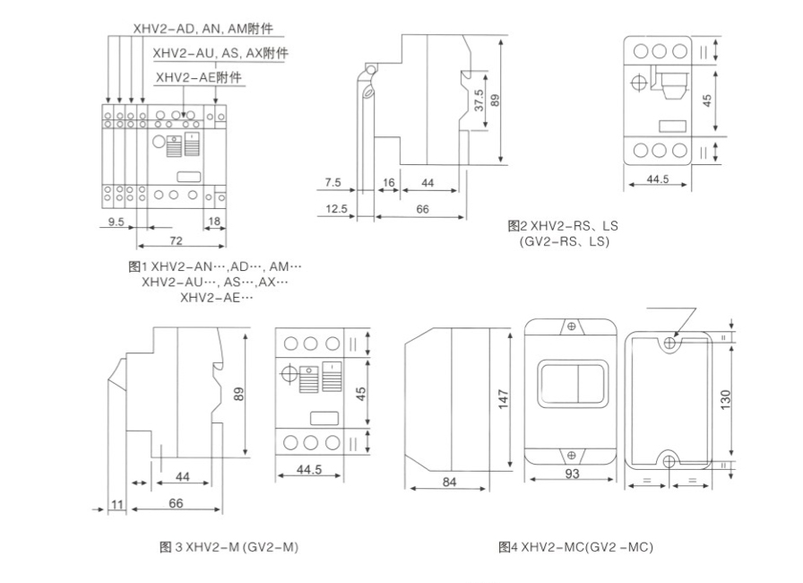
5.1 The outline and fixing dimension of breaker (GV2 Motor protection circuit breaker )(refer to chart2, 3).
5.2 The breaker (GV2 Motor protection circuit breaker) adopts the standard conductor rail installation, the conductor rail should meet the A2.1 TH35-7.5 type installation standard of JB6525.
5.3 The external installation of GV2 Motor protection circuit breaker (refer to chart1.4).
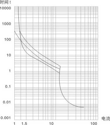
4.12 The characteristic curve of disjointing (refer to chart 5) the average work time according to the multiple of commuting current

Main technical parameters
1. Rated insulation voltage Ui(V): 690;
2. Rated work voltage Ue(V): 230/240, 400/415, 440, 550, 690;
3. Rated frequency Hz: 50/60;
4. The grade rated current of shell Inm(A): 32;
5. The rated voltage of disjointer ln(A)(j41 table 1);
6. The adjusting range of commuting current (A)(table 1);
7. The cutting capacity for rated limit short circuit lcu(kA)(table 7);
8. The cutting capacity for rated work short circuit lcs(kA)(table 7);
9. The bearable voltage for rated shock Uimp(V): 8000o
The characteristic of over-current action protection.
Table 7
| Rated current ln(A) | Adjusting rage of commuting current | ICS The cutting capacity for rated limit short circuit leu, the cutting capacity for rated work short circuit les | The distance of arcs (mm) | |||||||||
| 230/240V | 400/415V | 440V | 500V | 690V | ||||||||
| lcu(kA) | lcs(kA) | lcu(kA) | lcs(kA) | lcu(kA) | lcs(kA) |
lcu(kA) |
lcs(kA) | lcu(kA) | lcs(kA) | |||
| 0.16 | 0.10-0.16 | 100 | 100 | 100 | 100 | 100 | 100 | 100 | 100 | 100 | 100 | 40 |
| 0.25 | 0.16-0.25 | 100 | 100 | 100 | 100 | 100 | 100 | 100 | 100 | 100 | 100 | 40 |
| 0.4 | 0.25-0.4 | 100 | 100 | 100 | 100 | 100 | 100 | 100 | 100 | 100 | 100 | 40 |
| 0.63 | 0.4-0.63 | 100 | 100 | 100 | 100 | 100 | 100 | 100 | 100 | 100 | 100 | 40 |
| 1 | 0.63-1 | 100 | 100 | 100 | 100 | 100 | 100 | 100 | 100 | 100 | 100 | 40 |
| 1.6 | 1-1.6 | 100 | 100 | 100 | 100 | 100 | 100 | 100 | 100 | 100 | 100 | 40 |
| 2.5 | 1.6-2.5 | 100 | 100 | 100 | 100 | 100 | 100 | 100 | 100 | 3 | 2.25 | 40 |
| 4 | 2.5-4 | 100 | 100 | 100 | 100 | 100 | 100 | 100 | 100 | 3 | 2.25 | 40 |
| 6.3 | 4-6.3 | 100 | 100 | 100 | 100 | 50 | 50 | 50 | 50 | 3 | 2.25 | 40 |
| 10 | 6-10 | 100 | 100 | 100 | 100 | 15 | 15 | 10 | 10 | 3 | 2.25 | 40 |
| 14 | 9-14 | 100 | 100 | 15 | 7.5 | 8 | 4 | 6 | 4.5 | 3 | 2.25 | 40 |
| 18 | 13-18 | 100 | 100 | 15 | 7.5 | 8 | 4 | 6 | 4.5 | 3 | 2.25 | 40 |
| 23 | 17-23 | 50 | 50 | 15 | 6 | 6 | 3 | 4 | 3 | 3 | 2.25 | 40 |
| 25 | 20-25 | 50 | 50 | 15 | 6 | 6 | 3 | 4 | 3 | 3 | 2.25 | 40 |
| 32 | 24-32 | 50 | 50 | 10 | 5 | 6 | 3 | 4 | 3 | 3 | 2.25 | 40 |
1 The action characteristic of breaker(GV2 Motor protection circuit breaker) when every phase load is in balance.
Table 8
| The multiple of rated current | Starting state | Stipulated time | Due result | The temperature of ambient air |
| 1.05 | Cold state | tN2h | No disjointing | |
| 1.2 | Hot state (rises up to the stipulated current after following the test of No 1) | t<2h | Disjointing | +40°C ±2°C |
| 1.5 | One-time commuting current Starts after the bot balance | t< 2min | Disjointing | |
| 7.2 | Cold state | 2<t〈10s | Disjointing |
2. The action characteristic of breaker(GV2 Motor protection circuit breaker) when every phase load is in balance (phase-broken).
| The multiple of rated current | Starting state | Stipulated time | Due result | The temperature of ambient air | |
| Any two phases | The third phases | ||||
| 1.0 | 0.9 | Cold state | tw2h | No disjointing | +40°C ± 2°C |
| 1.15 | 0 | Hot state (rises up to the stipulated current after following the test of No 1) | t<2h | Disjointing | |


